Create logic diagram
The local logic screen
After you have setup your gateway and added sensor to it is time to do something with it. You can control actuators responding on the input from your sensors, and send alarms when something in the process controlled by your IoT devices configuring it from the local logic panel.
To go to the local logic panel go to the ubiworx broker interface, click on a gateway to enter in the sensor dashboard and click on the local logic menu
You will be presented with the following screen
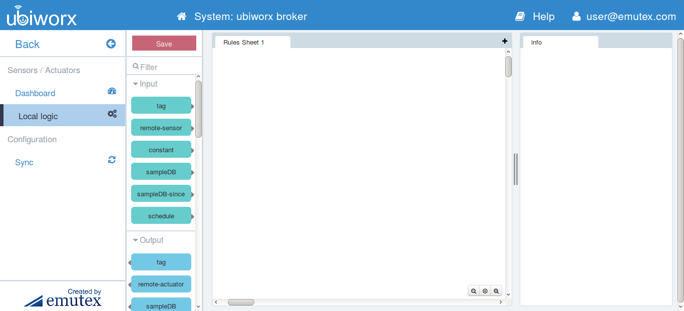
gateway logic panel
Here you have on the left a list of all the possible logical blocks that you can use with ubiworx, on the center a panel to create your logic diagram and on the right an help that shows you what the particolar block that you selected do and what are his parameters
Note
For more information about available logic blocks go to this apendix.
Block diagrams rules
The logic block diagram respect the following rules:
Blocks can be only inputs, outputs, or processing blocks.
The processing of the blocks are event driven, so each block is processed only when some of its input change state or it is triggered by some external event such as a timer. After that each block that is connected to it will be executed accordingly.
So the execution order of the logic diagram is determined by the chain of events linking outputs to inputs and not to any other order such for example the position on the graphical configuration interface.
each block can have a maximum of two inputs. If more than two inputs are wired then the rest are ignored.
each block can have a maximum of one output. If more than two output are needed you can use for example a tag block.
for the block where the order of the input is important, the order which the inputs are considered are the vertical position of their source block in the graphical logic configuration canvas. So an input connected to a block that appears above another block connected will appear first in the input list.
Warning
If the execution of a rules block causes the output of the rule block to change, then any blocks with an input connected to that block will in turn be executed.
Warning
Rule blocks with more than one input will be executed whenever any of the inputs is updated.
If two inputs are updated at the same time then this will create two events and the rule block will be executed twice.
This could cause a problem for downstream blocks that rely on output updates for timing purposes. To solve this kind of problem you can use the resample block described below.
The tag block
Every input or output in ubiworx is passed along using tags. You can retrieve or store any value by inserting a tag block and putting the corresponding id in it. For example, if you want to get a sensor value, you only need to add a tag input and select the sensor that you want.
You can also use tags as variables by simply inserting a tag output block, giving it a name and connecting its input to some other blocks.
The only limitation are that the tag name cannot start with the $ sign and the _ sign because they are reserved to internal use.
A simple example
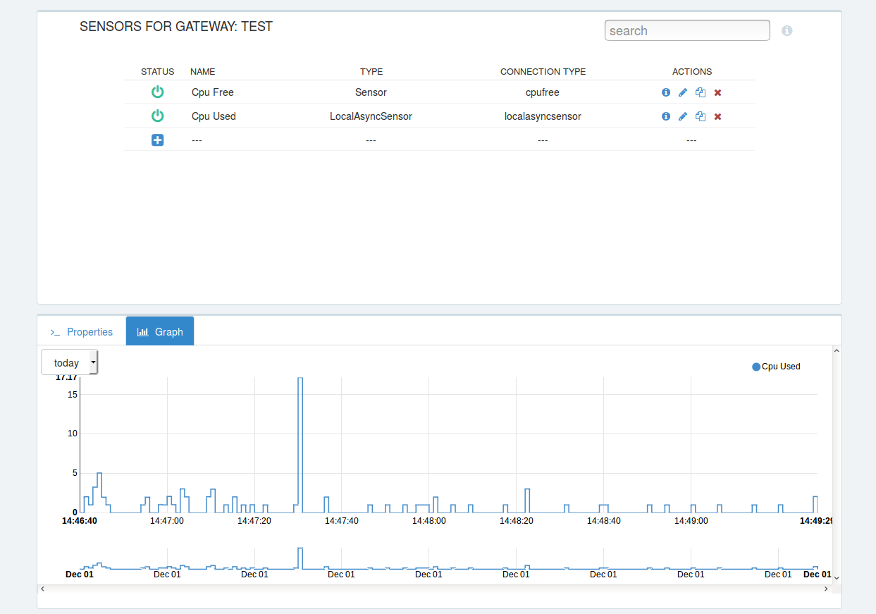
open your ubiworx gateway interface, select your gateway and add a CPU free sensor, giving it the name Cpu Free and the id cpufree01
add second Local Async Sensor and name it Cpu Used and the id cpuused01
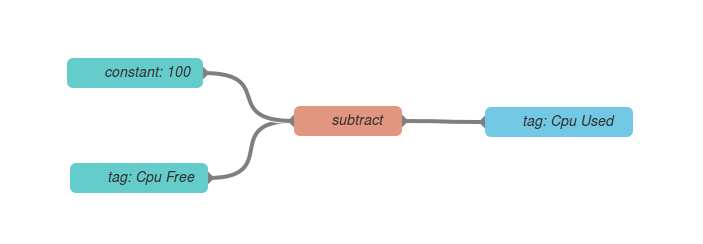
now go to the local logic page, add an input tag block, an output tag block, a subtract block and a input constant and connect like the image above
double click on each block and setup like this
- constant: set it to 100
- input tag name: set it to Cpu Free
- output tag name: set it to Cpu Used
click on save button and then click on the sync
Then go to the sensor Dashboard, if you click on the Cpu Used sensor and select graph you can see the graph of the utilization of the cpu
Some other logic examples
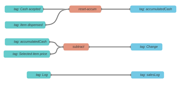
vending machine coin control logic
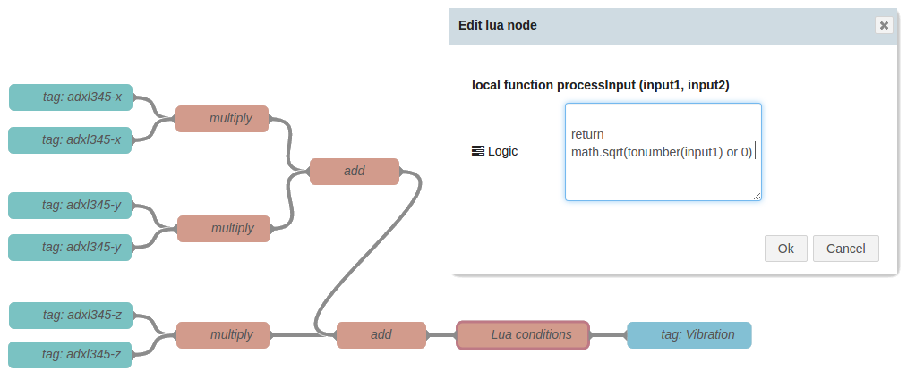
example of calculation and custom lua module